3D Printed Modulated Electron Bolus for Treatment of Basal Cell Carcinoma of the Eyelid
Olympic Medical Cancer Center Patient Case Study
This case study highlights:
- How Adaptiiv’s Modulated Electron Bolus (MEB) solution increases the clinical precision of external beam electron radiotherapy for basal cell carcinoma (BCC) of the eyelid.
- Two primary benefits of having onsite Point of Care (PoC) 3D printing:
- Increased precision and efficiency while producing lead shielding for
electron treatment. - Enables patient-specific phantom dosimetry with accurate geometry.
- Increased precision and efficiency while producing lead shielding for
Description
The patient was diagnosed with BCC of the eyelid and referred for external beam electron radiation therapy. The physician requested that a bolus, customized lead shielding, and tungsten eye shield be incorporated into the treatment plan to deliver 5500 cGy in 20 fractions to the target volume. Figure 1 displays the structures of interest on the CT data.
Design & Fabrication
Adaptiiv software was used to design a patient-specific MEB which conformed the 90% prescription isodose to the distal surface of the target volume for a 12 MeV electron beam. The MEB was then 3D printed using a fused deposition modelling (FDM) 3D printer with thermoplastic polyurethane (TPU) filament, a smooth and semi-flexible material. TPU was chosen to provide patient comfort and facilitate an MEB design that is compatible with the stem of the tungsten eye shield which passes through a hole in the bolus.
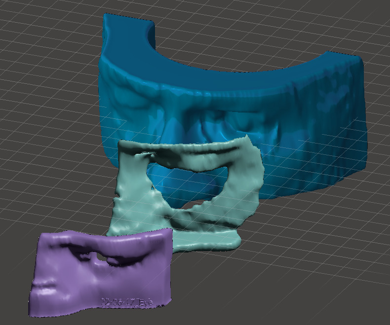
Customized lead shielding was designed to cover the ipsilateral area of the face from the zygoma (mid-cheek) to the brow, with an opening corresponding to the treatment field area. To increase precision and efficiency during the production of the patient’s customized lead shielding, a phantom shell structure (representing the patient’s external facial contour) and a surrogate lead shield structure were designed in the TPS and 3D printed using an FDM printer in rigid polylactic acid (PLA) filament. The 3D printed surrogate shield structure then acted as a guide to mold a 4 mm sheet of lead using a pair of c-clamp pliers. The molded lead shielding was placed on the phantom shell for a final fitting (Figure 2).
To provide accurate surface geometry for a phantom-based dosimetric measurement, a second 3D printed phantom part was produced representing the patient’s external facial contour with the tungsten eye shield carved out. This phantom part was produced using the same workflow and rigid material as outlined for the customized lead shielding-forming parts above.
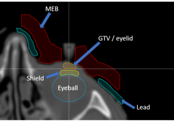
Figure 1: Patient CT data with structures of interest overlaid.
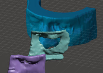
Figure 2: Models of the (1) patient phantom shell, (2) lead shielding, and(3) MEB.
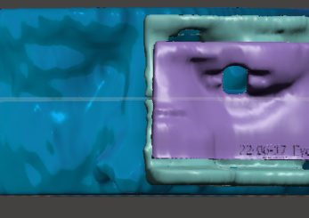
Figure 3: Second model view of the (1) patient phantom shell, (2) lead shielding, and(3) MEB.
Dose Calculation & Verification
The treatment planning dose of 5500 cGY over 20 fractions to the target region ranged from 106 – 125%, as calculated by the TPS (electron Monte Carlo model) and included the MEB.
Since the target area (eyelid) is positioned directly upstream of the tungsten eye shield and the electron Monte Carlo model typically calculates large hot spots on the entrance side of shielding material (due to electron backscatter), a 3D printed phantom dosimetry study was performed to verify the accuracy of the TPS-calculated dose in this region.
To do this, a dummy eye shield was placed onto the carved-out region of the second phantom part. Wax was formed on top of this to simulate the eyelid tissue, as shown in Figure 4. This setup was CT scanned with the 3D printed lead surrogate part and the MEB placed on the phantom. The dataset was brought into the TPS, densities were overridden to the appropriate values, and the dose was calculated.
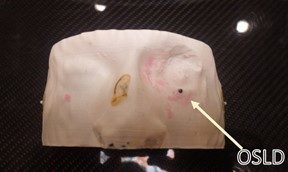
Figure 4A: The patient phantom shell displaying the location of the OSLD. CT setup BBs are also visible (2 lateral and one anterior).
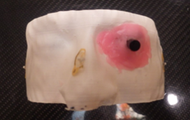
Figure 4B: The patient phantom shell after the dummy tungsten shield was placed and the simulated wax eyelid added.
Results & Findings
The MEB was able to conform the treatment plan’s 90% isodose to the target volume. The 3D printed parts supporting customized lead shielding production made shaping the shielding easier and more accurate to the patient’s external contour. The 3D printed phantom OSLD measurement showed excellent agreement with the TPS-calculated dose (within 1%). On day 1 of treatment, in vivo OSLD measured a dose of 327.1 cGy, 7% hotter than the expected 305 cGy. The MUs were scaled down by 7% for the remainder of the treatment.
Summary
- Adaptiiv software was used to design a patient-specific modulated electron bolus that was 3D printed.
- Customized lead shielding was fabricated by forming a sheet of lead to a 3D printed surrogate structure that had been created in the TPS.
- A 3D printed representation of the patient’s external contour was used to enable a phantom dosimetry study, confirming TPS-calculated dose in an area influenced by electron backscatter.