Adaptiiv On Demand TrueFlex Bolus for a VMAT Treatment for a Chin
Self Regional Healthcare Patient Case Study
Overview/Description
Adaptiiv Medical Technologies Inc. (Adaptiiv) offers cancer centers regulatory cleared software to design and 3D print patient-specific radiotherapy accessories.
This case is a great illustration of how Adaptiiv’s software can be effectively used in clinical radiation oncology through the creation of a TrueFlex bolus for VMAT treatment. This case showcases how a custom 3D-printed bolus enables a uniform dose distribution for a challenging anatomical site, while maintaining patient comfort.

Patient History
88-year-old female was treated at Self Regional Healthcare to manage squamous cell carcinoma of the skin after Mohs micrographic surgery to the chin. Deep resection to mandible periosteum, multiple (+) margins.
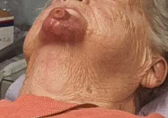
Figure 1. (A): prior to Mohs surgery
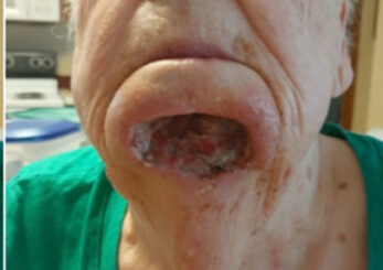
Figure 1. (B): post Mohs surgery
Design & Fabrication
The primary objective for the patient in this case was to achieve a uniform dose to the chin. The patient was initially simulated with a custom head mask.
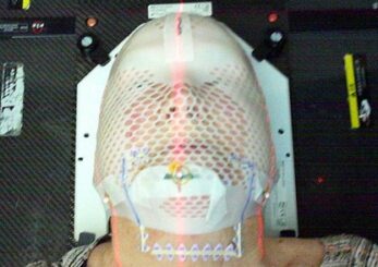
Figure 2. (A): Showing the initial simulation setup images with marker wires to define the initial CTV/PTV planning area
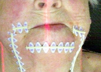
Figure 2. (B): Showing the initial simulation setup images with marker wires to define the initial CTV/PTV planning area
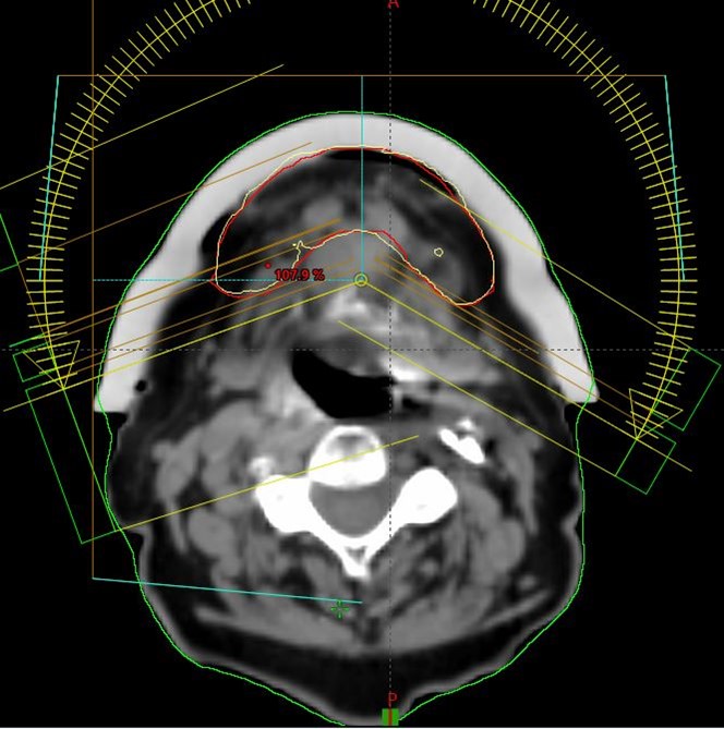
The dosimetrists went through a number of iterations of plans with the physician and physics to develop the optimal plan for this patient’s complex PTV setup. The decision was made to use a 1.0 cm bolus and use VMAT 6MV FFF photons for treatment. Figure 2 – This image set was used to create a uniform bolus with a thickness of 1.0 cm which was designed in the Treatment Planning System (TPS). The CT DICOM data and RT structure set were then sent to Adaptiiv’s 3D Bolus software, where the DICOM images of the bolus were converted to a stereolithography file. The design was then submitted as a mould using the Adaptiiv On Demand (AOD) service.
The mould design was automatically sent to Adaptiiv’s manufacturer, HP, leveraging the Multi Jet Fusion technology to 3D print the mould using rigid PA12 material. The mould was filled with EcoFlex 00-30 silicone to produce the TrueFlex bolus. Silicone bolus is known for its soft touch and high flexibility, making it ideal for patient comfort while ensuring conformality to a large surface coverage.
To guarantee the quality of the TrueFlex bolus, the AOD service performed quality assurance checks, ensuring that the physical density and spatial fidelity of the bolus were well within the specified tolerances.
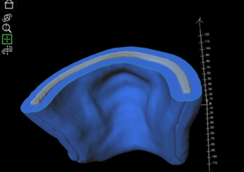
Figure 3. (A): The TrueFlex two-piece mould shown in blue, and the bolus material shown in translucent grey
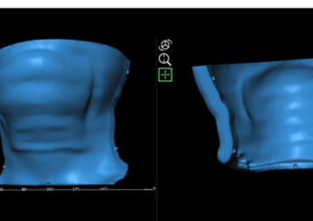
Figure 3. (B): the separated pieces of the mould showing the alignment guides to ensure the two pieces are put together accurately
After the custom bolus was received the patient was re-simulated using the initially created mask with the bolus in place. In order to ensure optimal fit on a treatment daily basis the mask was cut out. The patient was re-scanned with this new setup.
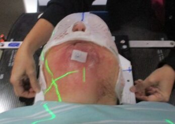
Figure 4. (A): Final planning CT setup with custom bolus
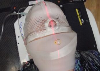
Figure 4. (B): Final planning CT setup with custom bolus
Dose Calculation & Verification
This newly acquired CT image set was used for the final plan creation. The bolus was included in the body contour. The patient received 60 Gy over 30 fractions normalized to the PTV volume utilizing VMAT technique and 6MV FFF photons. Dose conformity to the PTV was excellent.
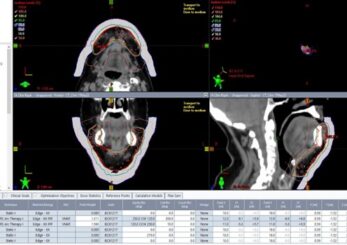
Figure 5. (A): VMAT plan in Eclipse TPS: Screenshots showing prescription isodose line conformity (yellow) with PTV (red)
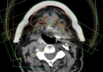
Figure 5. (B): VMAT plan in Eclipse TPS: Screenshots showing prescription isodose line conformity (yellow) with PTV (red)
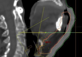
Figure 5. (C): VMAT plan in Eclipse TPS: Screenshots showing prescription isodose line conformity (yellow) with PTV (red)
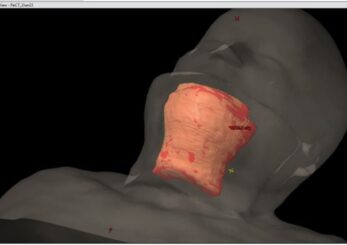
Figure 6: 3D Model View in TPS
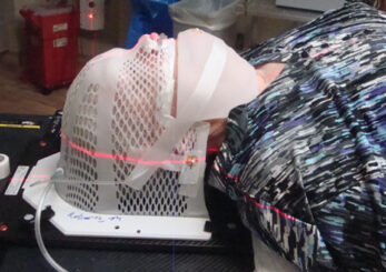
Figure 7: TrueFlex bolus placement on the patient for the treatment. Daily CBCT was used for setup verification
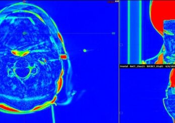
Figure 8: Example of image difference review for daily CBCT and planning CT showing minimal airgap
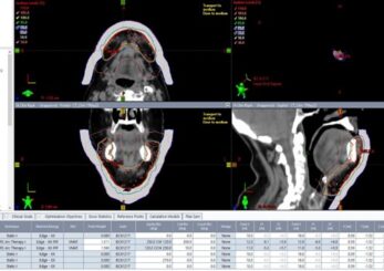
Figure 9: Daily CBCT review
OSLD measurements were performed during the first treatment fraction located at CAX and more inferior under the bolus. The measured vs, expected dose showed excellent agreement.
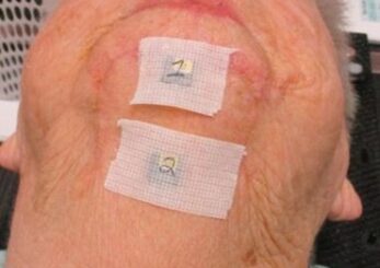
Figure 10: OSLD placement
Results & Findings
The patient tolerated the treatment very well.
Per Self Regional Healthcare therapists, the setup reproducibility was easy to reproduce on a treatment daily basis. It was easy to minimize the air gap and the bolus conformed really well. Bolus is much more flexible and stable over the whole treatment course than conventional bolus (in fact no comparison). Daily setup is much less time consuming due to the excellent fit of the bolus.
Images below show the healing process of the treatment area.
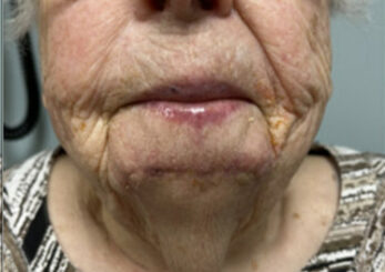
Figure 11. (A): beginning of XRT
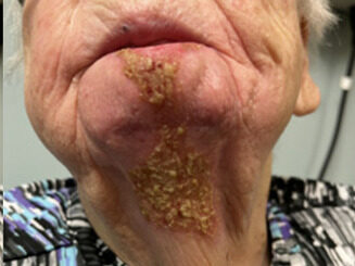
Figure 11. (B): 2 weeks post XRT
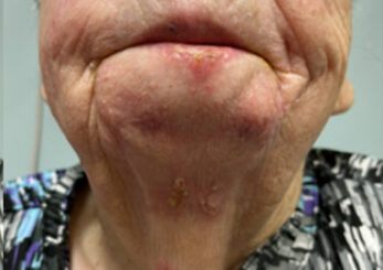
Figure 11. (C): 5 weeks post XRT
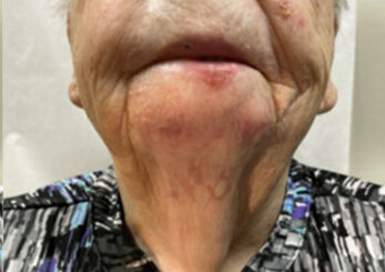
Figure 11. (D): 9 weeks post XRT
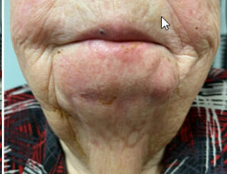
Figure 11. (E) 3 months post XRT, PET is clear
Summary/Benefits of Personalized 3D Printed RT Accessories
- Adaptiiv’s TrueFlex Bolus offered a soft and flexible solution, providing an excellent fit on the patient and minimizing air gaps.
- The bolus ensured consistent and reproducible placement during daily treatments, enhancing the overall patient experience and comfort.