Adaptiiv On Demand TrueFit Modulated Electron Bolus for Basal Cell Carcinoma of the Nose
Rocky Mountain Oncology Patient Case Study
Overview
Adaptiiv Medical Technologies Inc. (Adaptiiv) provides cancer centers with regulatory cleared software to design patient-specific radiotherapy accessories that can be 3D printed and ordered through Adaptiiv On Demand.
This case study highlights:
- How Adaptiiv’s Modulated Electron Bolus (MEB) solution increases the clinical precision of external beam electron radiotherapy for basal cell carcinoma (BCC) of the nose.
- The dosimetric benefits of using a MEB versus a uniform thickness bolus.

Patient History & Description
The patient was diagnosed with BCC of the left naris. The initial lesion was surgically removed with negative margins but a new lesion of the superior left naris presented. This second lesion was biopsied and also showed BCC. It was resected, this time with positive margins. Further resection was not viable and external electron beam radiation was then indicated for treatment of the left inner canthi area of the nose.
CTV diameter of approximately15 mm and max CTV depth of 5 – 10 mm. To be treated with external beam electron radiation therapy to a dose of 70 Gy / 35 fractions (200 cGy/fraction), with a prescribed treatment percentage of 90% (CTV coverage).
Diagnosis
Basal cell carcinoma of the left inner canthi region of the nose.
Fabrication & Treatment
The patient was CT simulated in an open face head and neck mask, acquiring scans with and without marker wire surrounding the lesion. The CTV was contoured by the physician on the with-wire scan and the external body contour was created using a lower threshold of -500 Hu on the without-wire CT scan. Contours were brought onto the without-wire CT scan that was used for planning.
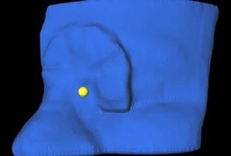
Figure 1: Visualization of the CAX reference point, created in Eclipse and imported into 3D Bolus.
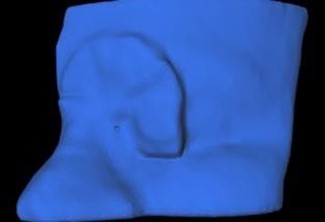
Figure 2: The cavity created using a cylindrical pocket of 1 mm depth and a 2 mm diameter.
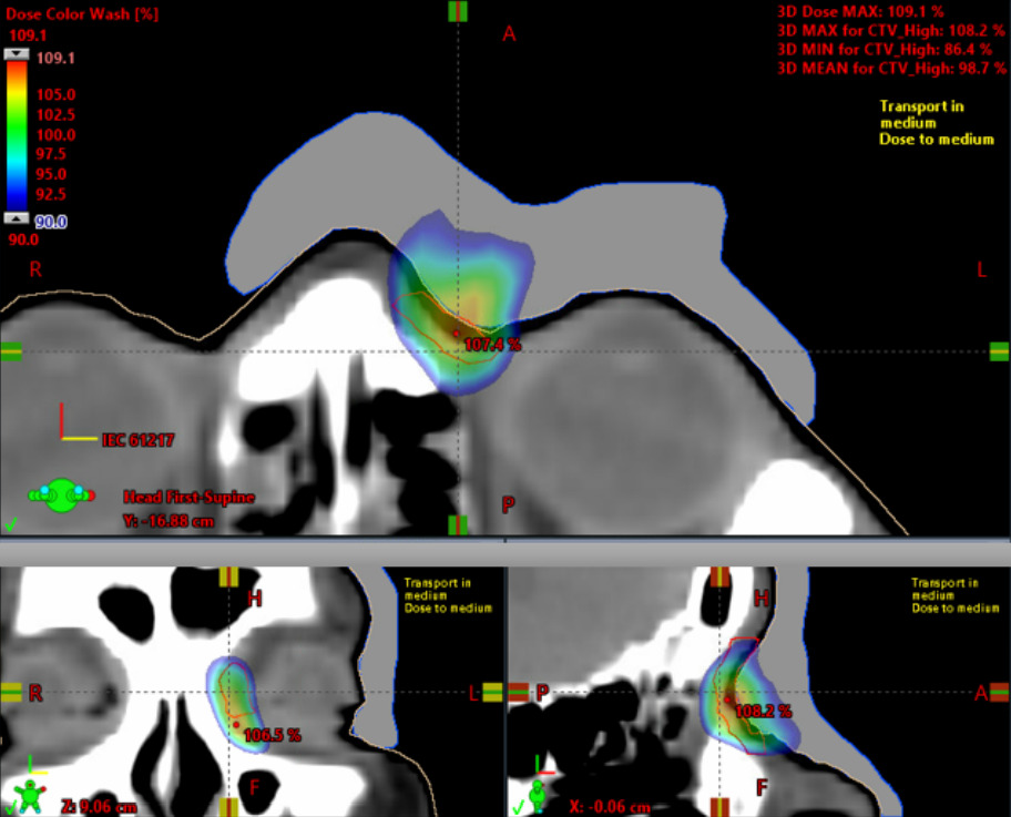
An initial mixed 6 MeV and 9 MeV plan was created with a 0.5 cm uniform thickness bolus for comparison to the subsequent Modulated Electron Bolus (MEB), as shown in Figures 3 & 4.
In Eclipse, a 9 MeV electron plan was created and the source to skin distance of the field set to 105 cm, allowing ample space between the end of the electron cone and the final modulated bolus positioned on the patient anatomy (the nose, cheek, and brow). The field was defined using an aperture with a 1 cm margin on the CTV. To plan the MEB, a 0.5 cm uniform thickness bolus was used for the initial dose calculation. The bolus density was set to a relative electron density (RED) of 1.06 / 74 HU, as commissioned to represent the Adaptiiv On Demand (AOD) TrueFit Bolus material. The uniform thickness bolus covered a ≥ 2 cm margin beyond the field edge in all directions except where it wrapped the contralateral nose just enough to provide anchoring for the bolus during treatment setup.
The dose distribution was normalized using 90% dose covering 98% of the CTV. The 90% isodose was converted to a structure and exported, along with the CTV and uniform thickness bolus, to Adaptiiv’s 3D Bolus software. In the software, an MEB was created using the 90% isodose structure, CTV, and the uniform 0.5 cm bolus as input. The MEB was exported back into Eclipse to calculate the final dose, verify good coverage (98%) and confirm conformity of the 90% isodose line to the CTV.
Figure 3: Dosimetric evaluation of a 9 MeVelectron plan with an Adaptiiv MEB.
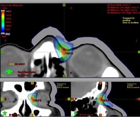
Figure 4: Dosimetric evaluation of a mixed energy (6 + 9 MeV) electron plan with a 5 mm bolus.
The MEB was then ready for post-processing and a central axis (CAX) reference point was placed on the beam-facing surface of the MEB in Eclipse. Adaptiiv’s Advanced Postprocessing Dosimetry tool, within 3D Bolus software, was then used to add a cavity to the outer surface of the bolus at the CAX reference point. The cavity was a cylindrical shape with a 2.0 mm diameter and 1.0 mm depth. The small cavity created in the bolus is dosimetrically negligible and allows the bolus to be positioned consistently and accurately, relative to the CAX.
The TrueFit bolus was ordered through the 3DBolus software using the Adaptiiv On Demand (AOD) service. TrueFit bolus are produced from thermoplastic polyurethane (TPU) powder via a process which includes direct 3D printing with an HP Jet Fusion 5200 printer, post processing for cooling and excess powder removal, and manufacturer-specified quality assurance. The 3D printing follows a controlled and validated process to ensure the end device meets clinical acceptance criteria as specified in the TrueFit Product Information Sheet.
Manufacturer-specified quality assurance includes a mass measurement to ensure consistent device density and an optical scan to ensure accurate device geometry relative to the design.
Dose
70 Gy / 35 fractions (200 cGy/fraction), with a prescribed treatment percentage of 90% (CTV coverage).
Results/Findings
The dose is much more conformal using the MEB, as well as improving on just about every other dosimetric aspect. The max plan dose with the 9 MeV MEB plan was 109.1% and the final source to modulated bolus distance was 103.5 cm. The max plan dose with the mixed energy (6 MeV + 9 MeV) uniform 0.5 cm bolus plan was 119.5 %. The MEB reduced the max dose by nearly 10%. The 90% isodose line only goes a few tenths of a cm beyond the target volume using the MEB, while it extends over 1 cm with the uniform thickness bolus.
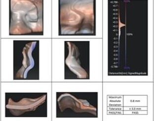
Figure 5: Certificate of Analysis: Spatial fidelity analysis ensures printed part meets our internaltolerance of 3 mm.
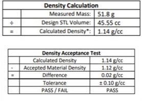
Figure 6: Certificate of Analysis: A density calculation ensures that the printed part meets our internal density tolerance.
Manufacturer quality assurance for this bolus passed relative to all acceptance criteria, showing spatial accuracy (max abs pt-pt deviation) of 0.8 mm and density accuracy of +0.02 g/cc (vs. established 1.12 g/cc for TrueFit).
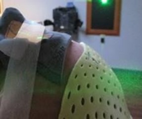
Figure 7: The bolus did lift slightly from the patient’s face on the lateral edges but, by using tape to secure the bolus to the cheek, this lifting was mitigated.
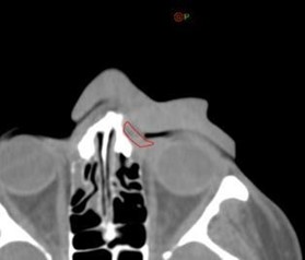
Figure 8: The first day CBCT showed a small air gap of 1 mm between then bolus and the patient near the eyelid; but overall, the bolus showed an excellent fit.
A MOSFET reading was taken during a subsequent treatment fraction, located at CAX under the bolus. The measured dose showed excellent agreement with the expected dose, at only +2.4% (measure dose 242.5 cGy vs. planned dose 236.9 cGy).
Summary
- The TrueFit bolus was easily ordered using the Adaptiiv On Demand service within the3D Bolus software.
- The RMO-commissioned relative electron density value used to represent the TrueFit bolus material was 1.06 (74 HU).
- The TrueFit patient-matched bolus allows for better fitting to patient anatomy, especially for complex geometry such as the inner eye and nose.
- Using a dual CT scan acquisition protocol, one with wires and one without, made the External Body and Bolus structure creation more efficient, accurate and robust to staff proficient / trained for complex contouring.
- The auto-generated External Body contour was created in Eclipse using a 500 HU threshold with a Smoothing Level of 1. This ensured the bolus was not too tight, but still captured the high curvature of the nose.
- The MEB provided ~ 10% reduction in the max plan dose.
- The dose was more conformal using MEB, as well as improving on several other dosimetric metrics.
- The Radiation Therapists were able to position the MEB confidently, accurately, and reproducibly every fraction.
- A MOSFET reading at the CAX showed a +2.4% agreement with the Eclipse point dose.