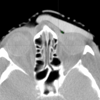
Comparison of Flexible Silicone Bolus to 3D Printed Rigid Bolus
Nova Scotia Health Patient Case Study
This case study illustrates designing and fabricating silicone bolus using the Adaptiiv software solution. This flexible silicone bolus fabrication process was then compared to the fabrication process of a rigid 3D printed bolus to determine whether it yielded comparable or improved plan metrics for treating an inner canthus tumour.
Fabrication and Treatment
Target volumes were contoured in the Eclipse planning system (v13.6, Varian Medical). Electron plans were generated with a bolus contour modified to optimize dose distribution. The bolus contour was exported, and the rigid bolus was printed using a Taz 5 3D printer. To produce the silicone bolus, a 4 mm outside wall structure (mould) was applied to the bolus contour using Adaptiiv’s mould feature, which was exported and printed. Two-part silicone rubber was mixed, then poured into the mould and allowed to cure.
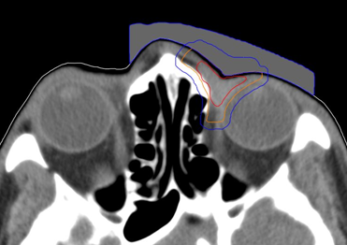
Figure 1: Customized bolus structure with preliminary target volumes GTV (red), CTV (orange), PTV (blue).
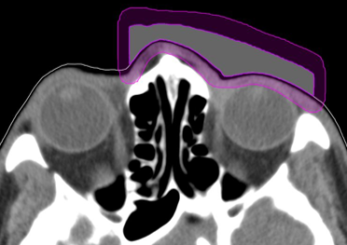
Figure 2: Customized bolus structure showing 4 mm wall structure (purple).
CT images were acquired with and without an internal eye shielding (IES) for the 3D printed rigid and flexible silicone bolus. The rigid bolus included a soft bolus plug over the eye to allow placement of the IES.
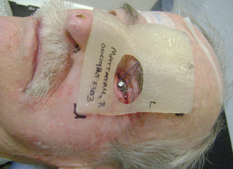
Figure 3: Internal eye shield and 3D rigid bolus placement.
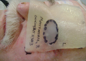
Figure 4: 3D rigid bolus with soft bolus plug.
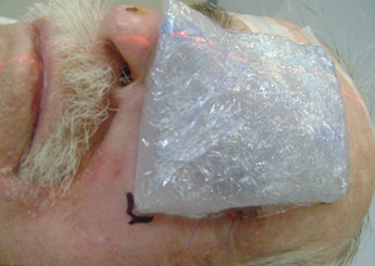
Figure 5: Silicone bolus placed on the patient.
Dose
Electron plans were normalized at Dmax using 12 MeV with a dose of 6000 cGy in 30 fractions prescribed to 100%. Evaluation metrics included: Dmax to 0.1 cc of the PTV, organ at risk (OAR) Dmax for the right/left lenses, optic nerves, eyes, and the left lacrimal gland.
Results
The data export and preparation times before 3D printing of both boluses were identical; however, more manual intervention was required for the silicone bolus. The rigid bolus required 4 hours to print, and support structures were removed and burrs sanded for patient comfort. The total time to produce the silicone bolus was 8 hours. The bolus mould required 1.5 hours to print, 0.5 hours for preparation and pouring of the silicone rubber, and 6 hours for curing.
Both showed good conformity to the body surface. The air gap volume over the inner canthus was 1.27 cc for the 3D rigid bolus, corresponding to the location of the soft bolus plug. The measured air gap volume under the silicone bolus in this same region was 0.24 cc.

Discussion
The silicone required a net increase of 4 hours longer to create compared to the rigid bolus. The additional time required was within the workflow guidelines of the department for the fabrication of customized bolus.
Both demonstrated good material homogeneity between 120-150 HU and 160-190 HU for the rigid and silicone boluses. PTV Dmax for the rigid bolus was 125.5% versus 116.6% for the silicone bolus. Dmax for OARs was comparable except for the left eye, which had a maximum difference of a reduction of 14% when using the silicone bolus.
While both boluses showed a close fit to the skin surface, the generic bolus plug introduced an air gap under the rigid bolus resulting in an overdose to the distal PTV and a higher dose to the underlying left eye. The soft and malleable nature of the silicone bolus allowed it to adjust to the contour of the bolus plug without modification.
The flexible and malleable nature of the silicone bolus required careful placement for daily treatment to ensure the proper fit. A CBCT was taken daily to verify the bolus position.
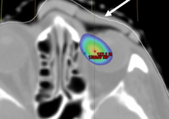
Axial view showing air gap and 115% isodose wash. Rigid bolus with soft bolus plug.
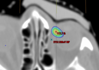
Axial view showing air gap and 115% isodose wash. Flexible silicone bolus.
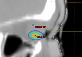
Saggital view showing 115% isodose wash. Rigid bolus with soft bolus plug.
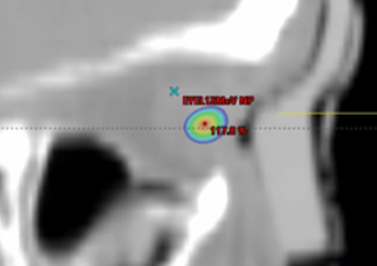
Saggital view showing 115% isodose wash. Flexible silicone bolus.
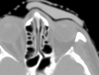
Axial images of silicone bolus. Planning CT image at simulation.
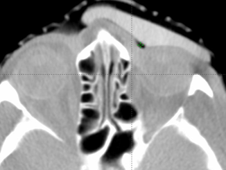
Axial images of silicone bolus. CBCT on treatment unit.
Summary
- The minimal additional workflow requirements for the fabrication of silicone bolus and comparable plan metrics with 3D rigid bolus make it a viable option for bolus application.
- The silicone bolus’s soft and malleable nature allowed the bolus to adjust the generic eye shield, resulting in a closer fit with smaller air gaps and a lower dose to the PTV and left eye.