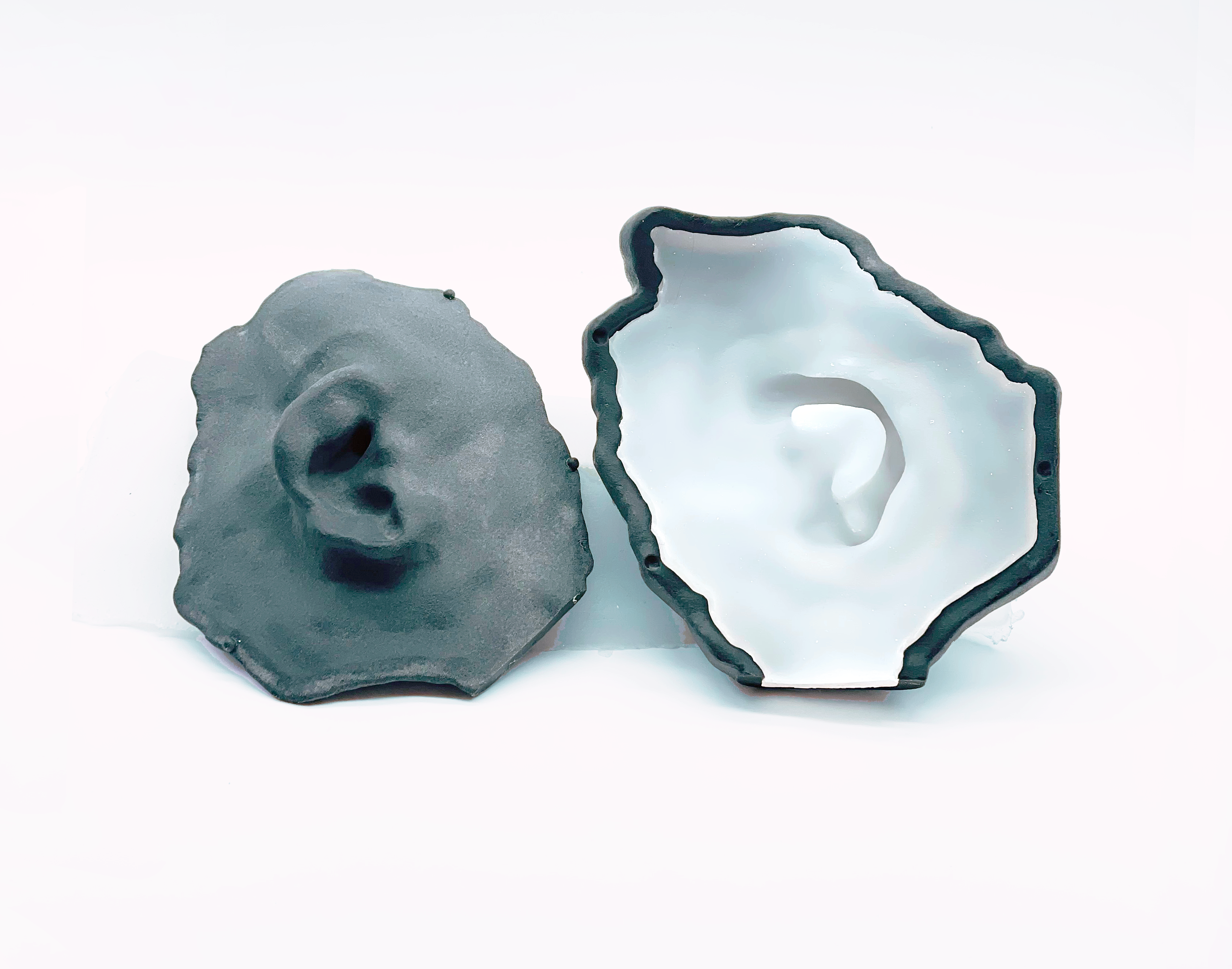
3D Printed Silicone Bolus Mould for the Ear
Nova Scotia Health Patient Case Study
This patient case demonstrates using Adaptiiv software to design a mould for a patient-specific silicone bolus. Silicone bolus is a conformal and flexible solution that assists in achieving the required dose build-up for radiation therapy. This approach has shown to be feasible in treating head and neck non-melanoma skin cancer¹ and offers dosimetry and workflow advantages².
¹ Canters et al. Clinical Implementation of 3D Printing in the Construction of Patient-Specific Bolus for Electron Beam Radiotherapy for Non-Melanoma Skin Cancer. Radiother Oncol 2016 121(1):148-153.
² Chiu et al. Three-dimensional Printer-Aided Casting of Soft, Custom Silicone Boluses (SCSBs) for Head and Neck Radiation Therapy. Pract Radiat Oncol 2018 8(3):e167-e174.
Patient History
An 81-year-old patient was treated at Nova Scotia Health and presented with squamous cell carcinoma of the left ear and preauricular area.
Fabrication and Treatment
Based on the patient’s CT, the clinical target volume (CTV) and planning target volume (PTV) was defined in the TPS (Eclipse v13.6) to include the left ear and preauricular area (Figure a). An initial 1 cm thick bolus was defined to cover the PTV with an approximate 2 cm margin (Figure b). The treatment plan was imported into Adaptiiv software, and a bolus model was generated based on the structure data.
A two-pieced shell-type mould was generated using the bolus structure data through Adaptiiv software’s mould feature (Figure c). The software’s cropping tool was used to crop the mould model on two planes to create an opening for filling and provide a flat surface to help with adhesion to the 3D printer bed (Figure d).
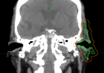
Figure A: CTV and PTV defintion.
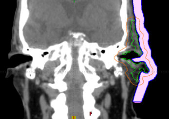
Figure B: Intial bolus in TPS.
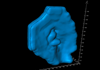
Figure C: Automated mould design in Adaptiiv 3DBolus software.
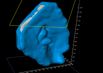
Figure D: Cropping for printing and filling.
Fabrication and Treatment (continued)
A set of hemispherical mortise/tenon interlocking alignment guides were added to the mould model to ensure the precise and easy fit of the two mould halves (Figure e). The completed bolus model (inside the mould) was exported to the TPS to confirm the bolus shape, location, and calculated dose.
Upon import to the TPS, the object is predefined with the relative electron density of the silicone material (Figure f), which is configurable in the Adaptiiv software. The planning approach for this case was to deliver 50 Gy in 20 fractions, using three co-planar, ipsilateral 6 MV VMAT arcs. The bolus mould was 3D printed using Fused Deposition Modeling (FDM) printing technology and polylactic acid (PLA), a rigid filament with low infill (e.g. 15%), to reduce the print time required.
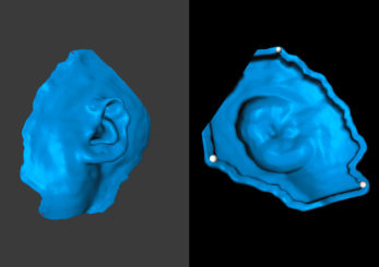
Figure E: Halif of mould model.
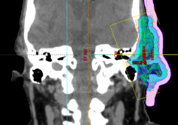
Figure F: Dose Calculation in TPS with final silicone bolus object.
After printing, the mould halves were assembled and sealed with caulking. A skin-safe silicone (EcoFlex™ 30) was poured into the mould and set for 4 hours, then released (Figure g). No desiccation was used for the evacuation of air during the curing process.
The final silicone bolus was fitted to the patient (Figure h), held in place using a gauze mesh, and the patient immobilization was formed over the bolus. A verification CT was performed to check the fit and uniformity of the bolus (Figure i). Although the step in Figure f can provide a final treatment plan with the assumption of accurate positioning, optionally, the treatment plan can be recalculated based on this CT dataset for comparison. During treatment, daily CBCT was used to assess the positioning and fit of the bolus (Figure j).
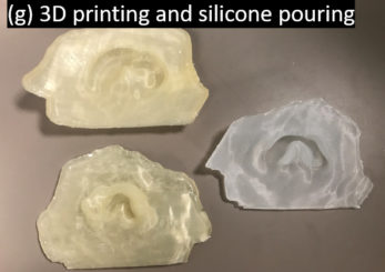
Figure G: 3D printing and silicone pouring.
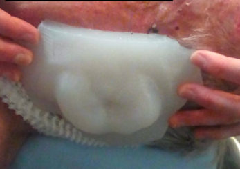
Figure H: Bolus application to patient.
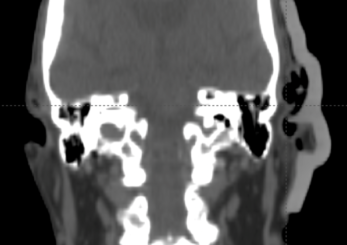
Figure I: Optional verification on CT.
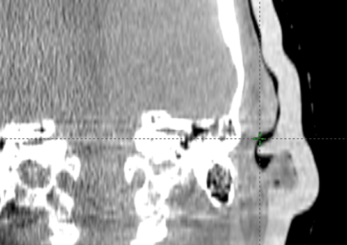
Figure J: Daily verification on CBCT.
Results and Findings
The Adaptiiv software application provided a fast and largely automated design of a silicone bolus, requiring approximately 10 minutes at the software step. The manufacturing process required approximately 8 hours for 3D printing, although this step requires no user interaction. The silicone pouring/removal process required 4 hours. The verification CT confirmed the accurate shape and positioning of the bolus (Figure i) relative to the designed object exported to the TPS (Figure f). The resultant silicone bolus was highly uniform on CT with a mean HU of 160 (approximate relative electron density of 1.13). No air voids were apparent. Daily CBCT showed consistent and accurate positioning throughout the treatment course (Figures k and l). Only 1 of 20 fractions required a correction of bolus positioning (Figures m and n).
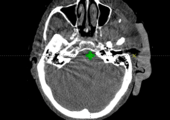
Figure K: CBCT on fraction one.
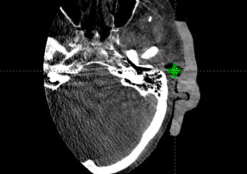
Figure L: Fraction 20 (final)
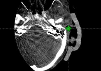
Figure M: CBCT on fraction 15, mispositioned.
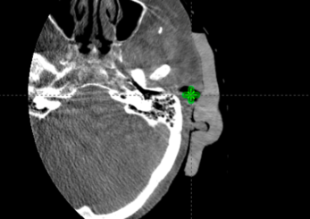
Figure N: CBCT on fraction 15, corrected after misposition.
Summary
- The Adaptiiv software application introduces an efficient solution to design a 3D printable mould for silicone bolus, requiring approximately 10 minutes in the software.
- Dedicated software tools enabled the necessary steps for mould fabrication, including cropping for 3D printing and silicone pouring, as well as the addition of alignment guides for the mould.
- The workflow provides a closed-loop approach, exporting the designed object back to the TPS, allowing verification recalculation of the plan, and incorporating the final bolus object.
- The manufactured bolus showed excellent uniformity and a mean relative electron density of 1.13, based on CT imaging.
- The bolus showed acceptable accuracy, with repositioning and re-acquisition of CBCT required only once in 20 fractions over the treatment course.
- The silicone bolus was easily positioned by therapists and well tolerated by the patient.